
Wastewater Network - ﺁﺯﻣﺎﯾشگاه پژوهشی پایش و پیش بینی هیدرولوژیکی و هواشناسی
Excess Energy Recovery in Water Supply Networks
Project Overview
Pressure control is one of the fundamental requirements for the safe and sustainable operation of water distribution networks. Excessive pressure can increase water leakage, cause pipe failures, damage network equipment, and reduce the service life of the system. In conventional practice, excess pressure is generally reduced using pressure-reducing valves, through which the available hydraulic energy is dissipated without being utilized.
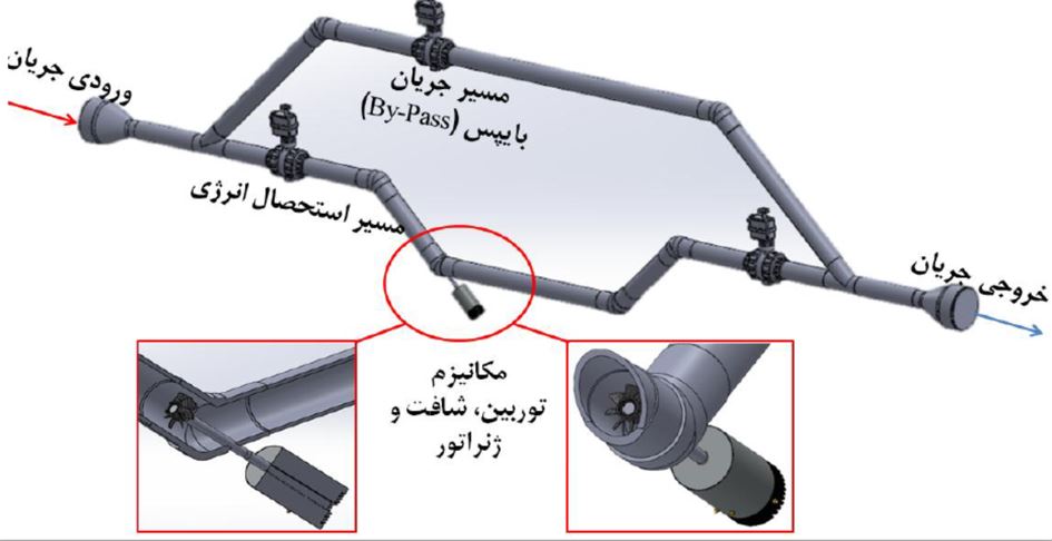
This project proposes a system for recovering excess hydraulic energy and converting it into electrical energy. The system comprises a microturbine, shaft, and generator installed within the flow path. While reducing excess pressure in the network, it also enables the generation of renewable electricity.
Project Objectives
- Recovering hydraulic energy that would otherwise be dissipated in water distribution networks;
- Controlling excess pressure without completely wasting the available energy;
- Generating clean electricity on site;
- Reducing the risk of equipment and pipeline failure caused by excessive pressure;
- Reducing the dependence of network equipment on external energy sources;
- Providing a scalable solution for the intelligent management of pressure and energy;
- Assessing the potential application of the system in other fluid transmission pipelines.
Proposed System Configuration
The proposed system consists of two main flow paths:
Energy Recovery Path
Water flows through an assembly comprising a turbine, shaft, and generator. The hydraulic energy of the flow is first converted into mechanical energy and subsequently into electrical energy.
Bypass Path
A parallel flow path is provided for use during maintenance, system failure, or shutdown. This path prevents interruption of the water supply when the energy recovery unit is taken out of operation.
Main Components
- Flow inlet and outlet;
- Energy recovery path;
- Microturbine;
- Power transmission shaft;
- Generator;
- Control valves;
- Bypass line;
- Performance monitoring and management system.
How the System Works
Water at excess pressure enters the energy recovery path. As the water passes through the turbine, it causes the turbine to rotate and transfers mechanical energy through the shaft to the generator. The generator converts the mechanical energy into electricity. Following the controlled reduction in pressure, the flow is returned to the main water supply line.
In the event of a system malfunction or when maintenance is required, the valves along the energy recovery path are closed and the flow is redirected through the bypass line. This arrangement ensures that operation of the main water supply line is not interrupted when the energy recovery unit is out of service.
Modelling and Feasibility Assessment
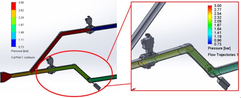
Hydraulic and numerical models were developed to evaluate the performance of the proposed system. The modelling results enabled the analysis of the following parameters:
- Pressure variations throughout the system;
- Flow paths and flow patterns;
- Pressure loss across the energy recovery unit;
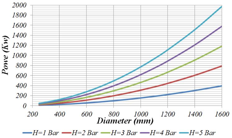
- Recoverable hydraulic power;
- Effects of pipe diameter and pressure head on energy generation;
- System performance under different flow conditions.
The feasibility studies demonstrated that installing the proposed system along existing water supply pipelines in Tehran could enable hydraulic power recovery under a range of flow conditions. The potential for recovering energy from existing pressure-reducing valves within the water and wastewater network of Tehran’s District 6 was also investigated.
Results: Recoverable Hydraulic Power from the Proposed System
Scope of Application
The application of the proposed system is not limited to water supply networks. With appropriate design modifications, its potential use in other fluid transmission systems may also be considered, including:
- Water transmission pipelines;
- Irrigation networks;
- Pressurized wastewater pipelines;
- Selected oil and gas transmission pipelines;
- Industrial systems with excess pressure.
Project Benefits
- Utilizing the energy available within the network without fuel consumption;
- Generating renewable energy and reducing energy losses;
- Enabling installation along existing pipelines;
- Maintaining uninterrupted water conveyance through the bypass line;
- Reducing excess pressure and protecting network equipment;
- Using relatively simple and maintainable components;
- Supporting the development of an online monitoring and management system;
- Enabling deployment at multiple locations throughout the network.
Project Achievement
The proposed project, including the system design and associated calculation tables, won first place at the national level in the National Renewable Energy Festival.